Instrument step parameters
Each step of a method/analysis appears in the Chromatography tab and can be configured by clicking on it. The Plate Layout step always appears first Though each instrument has its own set of parameters, they share common behaviors:
Default values are given to the different parameters in order to simplify the configuration for the user, meaning that you often won’t have to configure manually each step.
Instrument configuration windows have been designed to present the most important parameters first and to allow the user to access advanced parameters if needed (easy/expert paradigm).
Each instrument step has a Notes field and classic OK/Cancel buttons.
You can navigate back/forward through the analysis steps by using the corresponding buttons in the header of the step tooltips.
Here is the list of the different steps available:
Plate Layout
Define here the global parameters relative to the plate to be used and to the application.
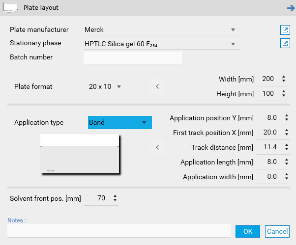
Plate Manufacturer
Choose the manufacturer of the plate for the analysis from the dropdown menu. If the desired manufacturer is not listed, the global list must be updated manually.
Stationary Phase
Select the type of plate material used in the analysis from the dropdown menu. If the required material is not listed, it must be added to the global list manually.
Batch Number
Enter the batch number of the plate used for this analysis as free text.
Plate Format
Select the plate size for the analysis from the dropdown menu.
For non-standard plate sizes, manually adjust the width (x-axis) and height (y-axis) values using the input fields. If manual dimensions are entered, the plate format will automatically be set to User.
Application Type
Choose from the following options: Band, Band Intertrack, Area, Area Intertrack, Spot, Spot Intertrack, or Manual.
Default Settings: The selected application type automatically applies corresponding default values, which can be reviewed in the extended menu.
Custom Adjustments: If you modify the default values, the application type will automatically switch to User.
For the Band, Area, and Spot modes, the Intertrack option is available. This setting ensures sufficient spacing between tracks, allowing the plate background to be detected as separate tracks.
Application Position Y [mm]
Specify the distance between the center of the application position and the lower edge of the plate in the Y direction.
Default: 8.0 mm.
First Application Position X [mm]
Specify the distance between the center of the first application position and the left-hand edge of the plate in the X direction.
Default: 20.0 mm.
Note
For manual devices, the spacing between tracks is determined by the notches on the Nanomat or spotting guide, defined as Raster in the General tab.
Important
Recommendation for Quantitative Evaluation: The first track should be positioned at least 20 mm from the plate edge.
Track Distance [mm]
Specify the spacing in the X direction between the centers of adjacent application positions.
Default: 11.4 mm.
Application Length [mm]
Define the length of the band(s) to be sprayed onto the plate.
Default: 8.0 mm.
Spotwise Application: For near-spotwise application, select 0 or 1 mm.
Important
Bandwise application should allow at least 10 passes of spray volume, band length, and dosage speed to maintain instrument accuracy.
Application Width
Specify the width of the band if Area or Area Intertrack is selected as the application type.
This setting allows for the application of larger sample volumes, which may require one or more focusing steps before chromatography begins.
Ensure the syringe capacity is sufficient to spray a complete area without refilling. Syringe size will limit the maximum allowable area.
Default: 4.0 mm.
Solvent Front Position [mm]
The position of the solvent at the end of the development step, measured from the lower edge of the plate. This value is critical as it defines the RF front position, ensuring accurate calculation and utilization of RF values during data processing and reporting.
Note
Be careful to configure the plate format according to the CAMAG instruments in use.
Note
When switching from/to Left/Center in the Track Assignment, the First track position X [mm] parameter is set.
CAMAG® HPTLC PRO Module APPLICATION
Define here the parameters relative to the execution of the HPTLC PRO Module APPLICATION.
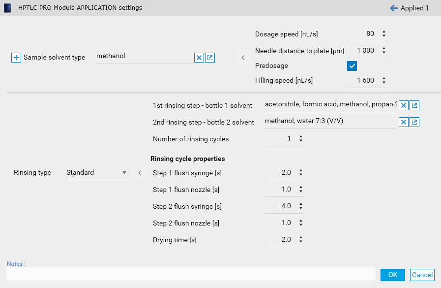
In most cases, an APPLICATION module step requires a single sample solvent type. If vials must be applied with different parameters, several Sets must be defined. A new set can be added via the + on the left:
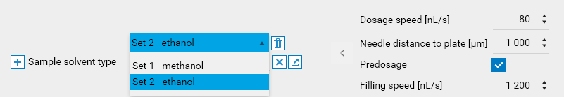
Each Set is identified by an order and the sample solvent type name on which it is based. The popup allows to add, edit and remove sets.
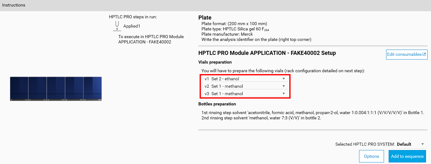
When the step contains several sets, each applied vial must then be associated with a set in the Instructions panel (see Instruction display):
ATS 4
Define here the parameters relative to the execution of the ATS 4 instrument. The window provides default solvent types and filling/rinsing quality configurations.
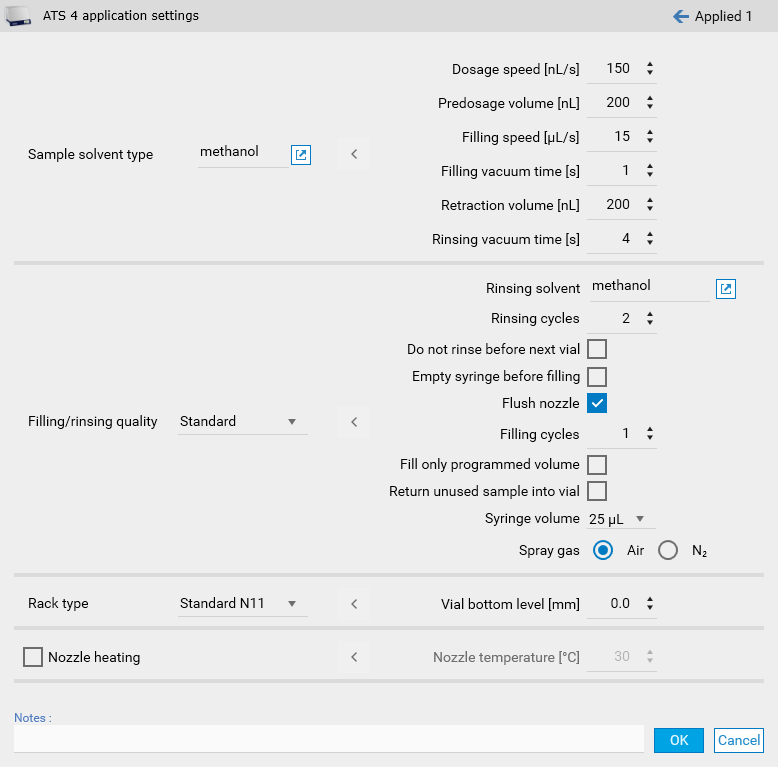
Sample Solvent Type
Choose from the following solvent types: acetone, ethanol, ethyl acetate, methanol, or water. The default solvent is METHANOL, which represents an ‘average’ parameter combination.
Equivalent Solvents
The table below provides examples of solvents similar to the selectable types:
Selection |
Equivalent Solvents |
|---|---|
water |
aqueous solutions at pH 7, without surfactants |
ethanol |
cyclohexane |
methanol |
toluene, chloroform, acetonitrile |
ethyl acetate |
N/A |
acetone |
hexane, diethyl ether, dichloromethane |
Important
Even trace amounts of dissolved substances can significantly alter the physical properties of the primary solvent. For instance, surfactants in water can have a notable effect.
Dosage Speed [nL/s]
The rate at which the sample is applied onto the plate. During bandwise spraying, the speed must be matched to the viscosity of the liquid and the gas flow to form a proper spray. Using bandwise application in conjunction with a combination of spray volume, band length, and dosage speed that does not permit at least 10 passes will not ensure the specified accuracy of the instrument.
Pre-Dosage Volume [nL]
The volume dispensed onto the waste plate to establish proper application conditions at the syringe needle tip.
Default: 0.2 µL.
Maximum Volume: The maximum volume that can be applied from a syringe equals the nominal volume of the syringe in use, minus the pre-dosage volume.
Filling Speed [µL/s]
The speed at which the sample solution is drawn into the syringe. The maximum filling speed depends on the liquid’s physical properties. Use a speed that avoids gas bubble formation in the syringe.
Filling Vacuum Time [s]
Vacuum applied to the syringe’s side port during the filling cycle at the vial position. This ensures proper filling of the application solution.
Low-Viscosity Solvents: Significant amounts can be removed quickly. Avoid settings that could empty the sample vial during this step.
Default: A value of 0 will cause the plunger to move up and down over the side port without delay, wasting a small sample volume.
Retraction Volume [nL]
The amount of sample pulled back into the syringe needle during lateral movement to reduce evaporation.
Rinsing Vacuum Time [s]
Vacuum applied to the syringe’s side port during the rinsing cycle at the waste position. This cleans the system using the rinsing solution.
Low-Viscosity Solvents: Ensure the rinsing well does not empty during this cycle.
Filling/Rinsing Quality
Choose between Standard or Quantification modes.
Default (Standard): The syringe is rinsed twice and filled once.
Quantification Mode: Recommended for low concentrations of substances that may adsorb to the syringe’s surfaces. In this mode, the syringe is rinsed twice and filled twice.
Rinsing Solvent
Choose the solvent to be used for rinsing the syringe.
Rinsing Cycles
Specify the number of rinsing cycles at the waste position using the selected rinsing solution. During each cycle, the syringe is filled with the rinsing solvent and then emptied.
Do Not Rinse Before Next Vial
Enable this option if rinsing between vials is not required.
Recommended Use: Useful when combined with the Fill Only Programmed Volume option to minimize sample use.
Note
Even with this option enabled, the syringe performs a filling and vacuum step.
Empty Syringe Before Next Vial
Use this option to pull up a specified volume into the syringe, introducing an air bubble. This may reduce reproducibility due to overspray caused by negative pressure at the needle tip.
Flush nozzle
Activates flushing of the nozzle for cleanliness.
Default: enabled.
Filling cycles
Number of times the filling process is performed.
Default: 1 cycle.
Fill Only Programmed Volume
Enable this option to minimize sample use.
Recommended Use: Best for non-critical applications where conserving sample is a priority.
Warning
Carryover may increase, and air bubbles in the syringe may reduce application reproducibility.
Return Unused Sample into Vial
Enable this option to return remaining sample volume to the vial.
Recommended Use: Ideal when conserving sample is critical.
Warning
Incompatible with Fill Only Programmed Volume, as their purposes conflict.
Syringe Volume [µL]
Select the appropriate syringe volume for your application.
10 µL: Best for quantification applications.
10 µL and 25 µL: Best for spotwise sample application.
25 µL and 100 µL: Best for bandwise sample application.
Important
Ensure the correct needle type (contact or spray) is attached for optimal performance.
Verify the syringe is properly installed to ensure accurate volume application.
Default Setting: A 25 µL syringe with a spray needle.
Spray Gas:
Choose the gas for spraying the samples: Air or Nitrogen (N₂).
Rack Type
The standard N11 rack type is the only available option.
Vial Bottom Level [mm]
Adjust the vial bottom level to control the needle’s penetration depth into the vial.
Default: 0.0 mm (for standard 2 mL vials).
Adjustments: - Increase penetration depth: Values > 0.0 mm. - Decrease penetration depth: Values < 0.0 mm (e.g., -0.1).
Important
Avoid contact between the needle tip and the vial bottom to prevent damage.
Nozzle Heating
This feature is available only if the connected ATS 4 includes the optional Heating of Spray Nozzle upgrade.
Temperature Settings
Choose a target temperature (30°C, 40°C, 50°C, or 60°C).
Note
Rack positions are defined in the Track Assignment
Linomat 5
Define here the parameters relative to the execution of the Linomat 5 instrument (semi-automatic application).
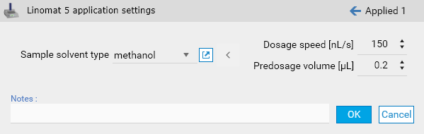
Sample Solvent Type
Choose from the following solvent types: acetone, ethanol, ethyl acetate, methanol, or water. The default solvent is METHANOL, which represents an ‘average’ parameter combination.
Equivalent Solvents
The table below provides examples of solvents similar to the selectable types:
Selection |
Equivalent Solvents |
|---|---|
water |
aqueous solutions at pH 7, without surfactants |
ethanol |
cyclohexane |
methanol |
toluene, chloroform, acetonitrile |
ethyl acetate |
N/A |
acetone |
hexane, diethyl ether, dichloromethane |
Important
Even trace amounts of dissolved substances can significantly alter the physical properties of the primary solvent. For instance, surfactants in water can have a notable effect.
Dosage Speed [nL/s]
The rate at which the sample is applied onto the plate. During bandwise spraying, the speed must be matched to the viscosity of the liquid and the gas flow to form a proper spray. Using bandwise application in conjunction with a combination of spray volume, band length, and dosage speed that does not permit at least 10 passes will not ensure the specified accuracy of the instrument.
Pre-Dosage Volume [nL]
The volume dispensed onto the waste plate to establish proper application conditions at the syringe needle tip.
Default Value: 0.2 µL.
Maximum Volume: The maximum volume that can be applied from a syringe equals the nominal volume of the syringe in use, minus the pre-dosage volume.
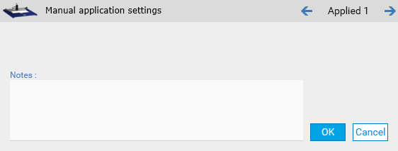
Manual application
Manual application step with any kind of manual application device:
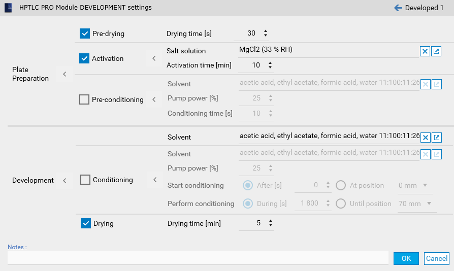
CAMAG® HPTLC PRO Module DEVELOPMENT
Define here the parameters relative to the execution of the HPTLC PRO Module DEVELOPMENT (single application).
ADC 2
Define here the parameters relative to the execution of the ADC 2 instrument (single application). The window provides some default development type parameters.
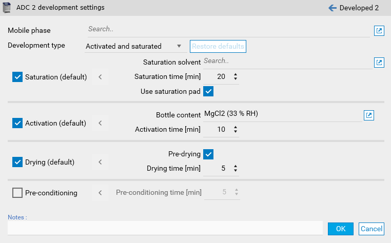
Note
When having several ADC 2 or ADC 3 steps, the solvent front position can be defined here and not only in the Plate Layout parameters.
ADC 3
Define here the parameters relative to the execution of the ADC 3 instrument (single application). The window provides some default development type parameters.
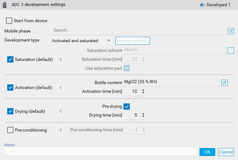
Note
When having several ADC 3 or ADC 2 steps, the solvent front position can be defined here and not only in the Plate Layout parameters.
Start from device will permit to start the execution of the step from the device. See Instrument step execution.
AMD 2
Define here the parameters relative to the execution of the AMD 2 (multiple applications). The General tab handles the configuration of the bottles and the instrument itself.
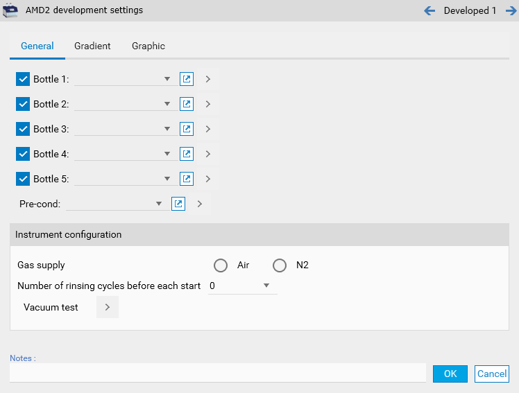
The Gradients tab contains the configuration of the gradients steps, with auto-fill options.
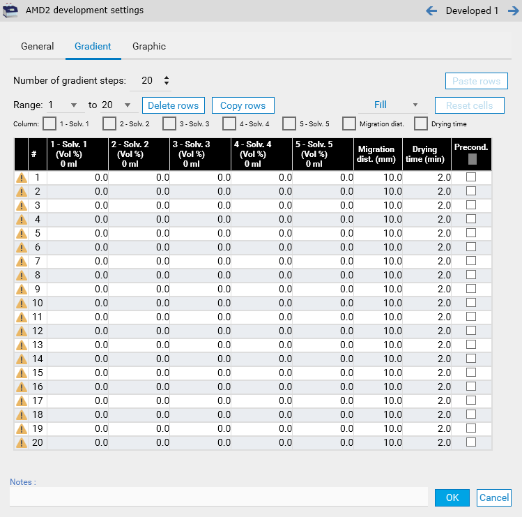
Note
The Graphic tab consists in a visual representation of the Gradients tab.
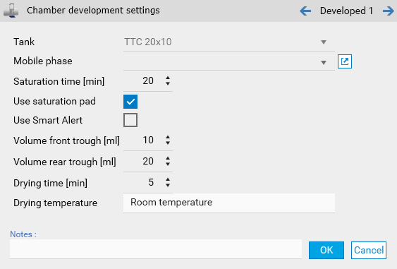
Chamber
Define here the parameters relative to the execution of a development in a glass development chamber.
CAMAG® HPTLC PRO Module DERIVATIZATION
Define here the parameters relative to the execution of the HPTLC PRO Module DERIVATIZATION.
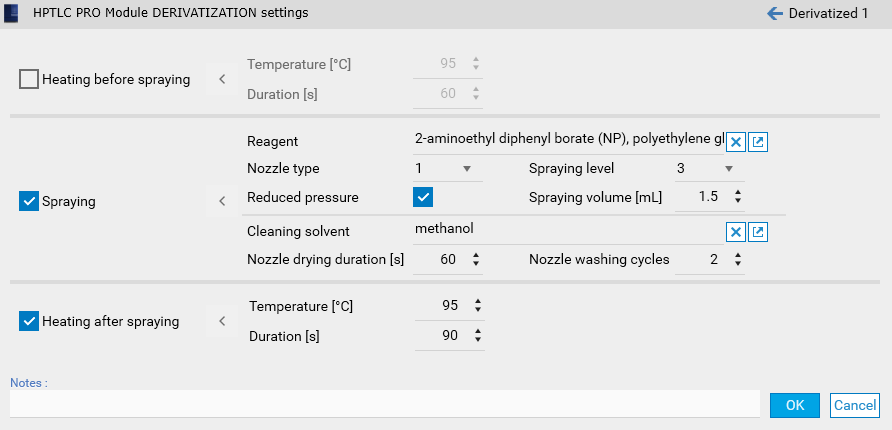
Note
Heating before spraying consists in the pre-heating of the HPTLC plate.
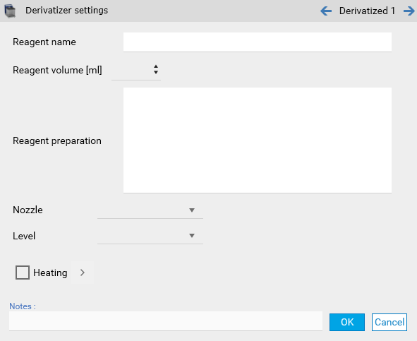
Derivatizer
Define here the parameters relative to the execution of the Derivatizer instrument.
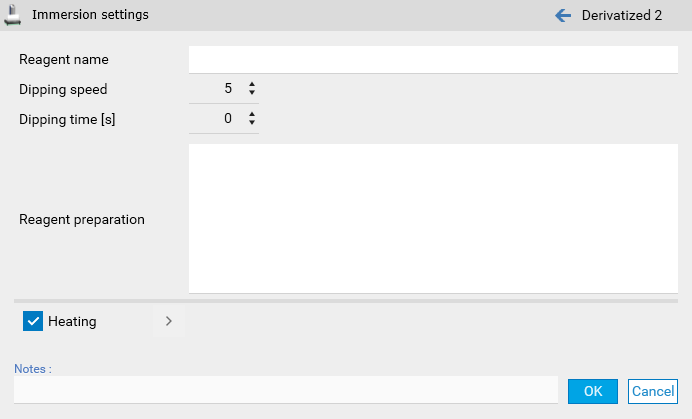
Immersion
Define here the parameters relative to the execution of a derivatization by dipping.
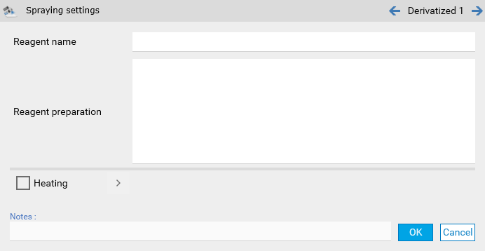
Spraying
Define here the parameters relative to the execution of a derivatization by spraying.
TLC Visualizer
Define here the parameters relative to the execution of a TLC Visualizer documentation step. A visualizer step can contain up to 5 images (called Illuminations), with the possibility to repeat them in a sequence.
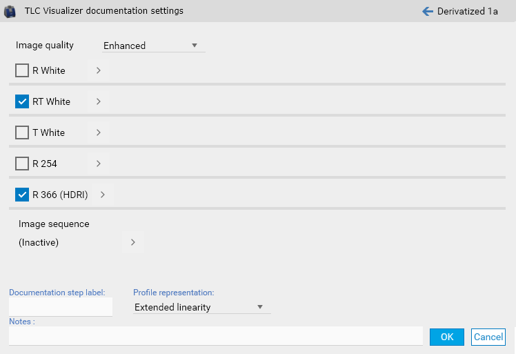
Note
The Documentation step label field can facilitate the identification of documentation step data when using them.
Note
The Visualizer High-Res documentation package option is required to take Enhanced images.
Note
The Profile representation mode can change how profiles are generated, see Extended Linearity.
TLC Scanner 4
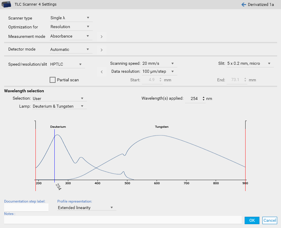
Scanner Type
Select the measurement mode from the dropdown menu:
Single λ:
Used for scanning at a single wavelength in absorption or fluorescence mode.
Multiple λ:
Used for automatically scanning at multiple wavelengths in absorption and/or fluorescence mode. Additional parameters must be configured to generate the desired scans.
Note
The Multi Wavelength Scanning option is required to use the multi-wavelength mode.
Spectrum:
If spectrum scanning is selected in the General tab, navigate to the Spectrum tab to configure the required parameters.
Note
The Spectrum Scanning option is required to use the spectrum mode.
Optimization For
Select the desired optimization from the dropdown menu:
Resolution
Optimized for maximum spectral resolution (5 nm bandwidth).
Light (Sensitivity):
Optimized for maximum light (20 nm bandwidth).
A 20 nm monochromator bandwidth enhances slit illumination but reduces spectral resolution.
Important
For normal measurements, always use Light. This is crucial when working with low substance quantities.
Rule: The more light and the slower the scan speed, the lower the detection limit.
For Multiple λ scans, select Resolution only if higher wavelength selectivity is essential for the task.
Measurement Mode
Choose between Absorption and Fluorescence modes:
Absorption:
Measures the difference between incident and absorbed light (100% - x).
Suitable for substances that absorb light at wavelengths between 190 nm and 900 nm.
Fluorescence (Excitation):
Measures the emitted light from substances excited by incident light of shorter wavelengths.
A cut-off filter must be placed in front of the photomultiplier to block shorter wavelength incident light.
Important
Do not scan fluorescence excitation spectra within 20–40 nm of the cut-off wavelength of the selected filter.
Advanced:
All options set per wavelength, see Wavelength(s) Applied.
Parameters Influenced by Measurement Mode:
Optical Filter:
Important
Available only if Fluorescence is selected
Options: None, K320, K400, K540, K790, User 1, User 2, User 3
Default: K400
Note
Choose a cut-off filter that permits emitted light to pass while ensuring the fluorescence excitation spectra are scanned no closer than 20–40 nm to the filter’s cut-off wavelength.
Detector Mode
Choose between Automatic and Manual modes:
Automatic Mode:
Can be used for both Absorption and Fluorescence scanning. The adjustment and optimization routines differ based on the scanning type.
Absorption scanning:
Performs a ZERO adjustment at the start position on the first track.
Warning
Avoid selecting a position that absorbs excessive light, as it may negatively impact automatic scanning results.
Fluorescence scanning:
Performs a QUICK scan across all tracks to identify the position emitting the most light, which is then used for signal optimization.
Manual Mode:
Use this option only if the results from Automatic Mode do not meet your requirements.
When Manual Mode is selected, the following parameters become available:
Quick Scan Start:
Specify the start position of the quick scan in the Y direction.
Default: 4.9 mm. This position should be free of substances but does not need to match the Scan Start Position Y.
Quick Scan End:
Specify the end position of the quick scan in the Y direction.
Default: 73.1 mm. This position does not need to match the Scan End Position Y.
Quick Scan Track:
Enter the track number for the quick scan. Default is all tracks.
Analog Offset:
Set the offset value for measurement. This extends the dynamic range of the AD converter below the zero line, allowing measurement of smaller absorption and fluorescence values than at the zeroing position.
Default: 10%.
Sensitivity:
Controls the electronic amplification of the analog signal.
Default: Automatic (recommended).
Note
Selecting too high a sensitivity may cause the AD converter to overrun. Manual optimization for spectra is challenging; Automatic is strongly advised.
0 Adjust Position Y:
Set the Y-position for zero adjustment. This position should be substance-free.
Default: 4.9 mm.
0 Adjust Track:
Specify the track number for zero adjustment. The range is from track 1 to the total number of tracks.
Default: track 1.
Speed/Resolution/Slit
Choose between HPTLC, TLC, or User modes.
Scanning Speed
Range: Select the scanning speed from the dropdown list.
Recommendation:
Lower speeds allow for more individual measurements to be averaged per data point, improving accuracy.
Speeds above 20 mm/s may not capture the detector’s full signal height and can slightly reduce measurement reproducibility.
Default Speed: 20 mm/s.
Important
Do not exceed 20 mm/s if overall reproducibility better than 2% is required or if performing a spectrum scan.
Data Resolution
Selection: Choose the resolution from the dropdown list.
100 µm/step: Suitable for HPTLC and normal TLC applications.
200 µm/step: Recommended for very wide fractions (20 µm/step and larger) in TLC.
Default Resolution: 100 µm/step.
Slit
Selection: Choose the desired slit size from the dropdown list (38 options available).
The selected slit is automatically aligned in the ray path when the scan begins.
Guidelines for Slit Selection
Spotwise Application: The slit should be larger (longer) than the width of the largest spot in the track.
Bandwise Application: Use the longest possible slit, ensuring it remains within 70–90% of the band length.
Default Slit: 5 x 0.2 mm, micro.
Micro and Macro Slits
The first two columns list MICRO-sized slits, while the third and fourth columns list MACRO-sized slits.
Example: The MICRO slit 4.0 x 0.45 and the MACRO slit 8.0 x 0.9 provide 66.7% of the available light at the specified wavelength and have a noise factor of 1.22.
Noise Factor: Indicates how much higher the noise level is at the selected slit size compared to the largest slit size, which delivers the maximum amount of light at the specified wavelength.
Slit Length (MICRO)
Slit Width (MICRO)
Slit Length (MACRO)
Slit Width (MACRO)
Relative Amount of Light [%]
Noise Factor
6.0
0.45
12.0
0.9
100.0
1.00
6.0
0.3
12.0
0.6
66.7
1.22
6.0
0.2
12.0
0.4
44.4
1.50
6.0
0.1
12.0
0.2
22.2
2.12
5.0
0.45
10.0
0.9
55.6
1.34
5.0
0.3
10.0
0.6
37.0
1.64
5.0
0.2
10.0
0.4
25.0
2.22
5.0
0.1
10.0
0.2
12.5
3.14
4.0
0.45
8.0
0.9
66.7
1.22
4.0
0.3
8.0
0.6
44.4
1.50
4.0
0.2
8.0
0.4
22.2
2.12
4.0
0.1
8.0
0.2
11.1
3.14
0.25
0.5
0.5
0.2
0.9
10.54
Partial Scan
Define the start and end positions for the scan along the Y-axis.
Default:
Start: 4.9 mm.
End: 73.1 mm.
Wavelength Selection
Selection: Choose between From substance table and User.
Lamp
Select the lamp that is best suited for the analytical task and wavelength to be used.
The following wavelengths can be used with each lamp:
D₂: 190–450 nm (Deuterium lamp).
W: 370–800 nm (Tungsten lamp).
D₂ and W: 190–800 nm (both lamps with automatic changeover).
Hg: Specific wavelengths (Mercury lamp).
Warning
If the TLC Scanner 4 lacks a mercury lamp and the parameters require one, the Scanner instrument cannot be selected to execute that step.
Stabilization:
The deuterium lamp requires about 5 minutes to stabilize after switching on.
The tungsten lamp requires about 1 minute.
Software Control:
The software keeps both D₂ and W lamps ignited if spectrum measurement requires both.
Wavelength(s) Applied
Single λ:
Enter the wavelength for the first scan.
Range: 190–900 nm.
Default: 254 nm.
Multiple λ:
When choosing multi-wavelength, define a pattern to apply.
Enter the wavelength increment to be used during a linear scan.
The calculated wavelengths will automatically appear in the Detector table of the Linear Scan tab.
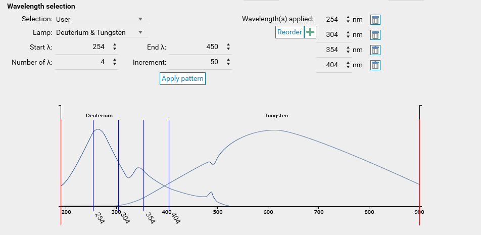
Note
An Advanced mode is also available, where the measurement mode, lamp and filter can be set independently for each wavelength.
Spectrum Parameters
Note
The Spectrum Scanning option is required to use the spectrum mode.
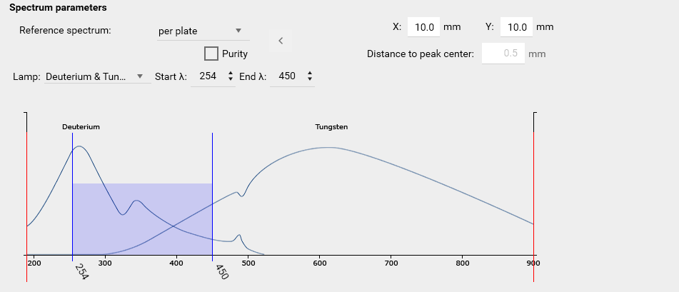
Reference Spectrum
Select the input mode for specifying the reference spectrum position(s) on the plate. Available options are:
Per Plate:
X Distance: Specify the distance from the left edge of the plate to the position where the reference spectrum is recorded and zero adjustment is performed.
Y Distance: Specify the distance from the lower edge of the plate to the position where the reference spectrum is recorded and zero adjustment is performed.
Per Track:
The reference spectrum is recorded, and zeroing is performed at the 1WL, 2WL, or MWL scan X position.
In Per Track mode, this process is repeated once for each track.
Purity
Enable Purity Measurement: Activate this feature to measure three spectra per fraction detected on the plate:
At the peak center.
At the peak start slope.
At the peak end slope.
Distance to Peak Center: Specify a fixed distance from the peak center for the additional spectra measurements.
Purity Section in Scanner Step:
Toggle visibility of the additional spectra and view a table displaying the correlation results.
Correlation Results:
r(s;m): Correlation between the start and middle spectra.
r(e;m): Correlation between the middle and end spectra.
Note
Both correlations are calculated using the sample Pearson correlation coefficient.
Lamp
Select the lamp best suited for the analytical task and wavelength:
D₂: 190–450 nm (Deuterium lamp).
W: 370–800 nm (Tungsten lamp).
D₂ and W: 190–800 nm (both lamps with automatic changeover).
Hg: Specific wavelengths (Mercury lamp).
Profile Representation
Choose between Classic and Extended Linearity, see Extended Linearity.
Note
The Documentation step label field can facilitate the identification of documentation step data when using them.
Common features
Importing analysis and method, especially when they are coming from foreign installations, may use global list items which are not defined in the current installation. In that case, the following warning appears:
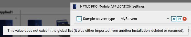
Note
This also happens when global list items were modified, see Files import.
For already executed analyses, the warning can be ignored. For not already executed methods or analyses, the value should either be changed or a new corresponding global list item should be added with the needed parameters.